Design lead: Musab Badahdah
Computational Specialist: Ali Tabatabie
Fabrication: Namthaja, Additive Manufacturing Solutions
Animation: Maral Hashemian
Computational Specialist: Ali Tabatabie
Fabrication: Namthaja, Additive Manufacturing Solutions
Animation: Maral Hashemian
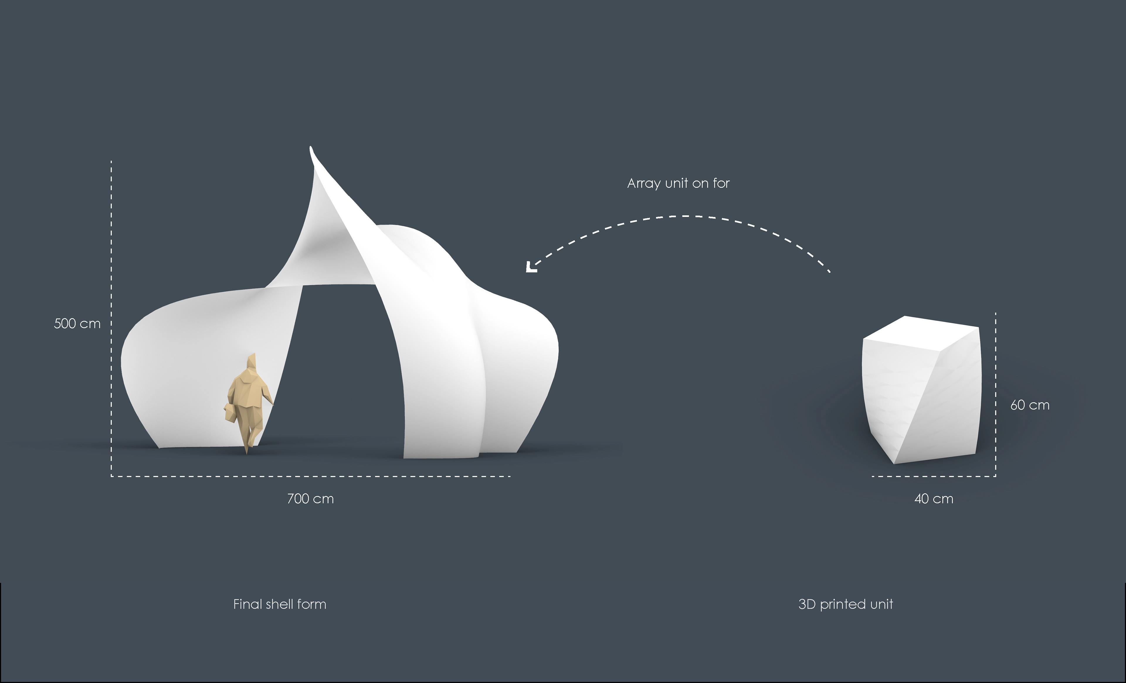
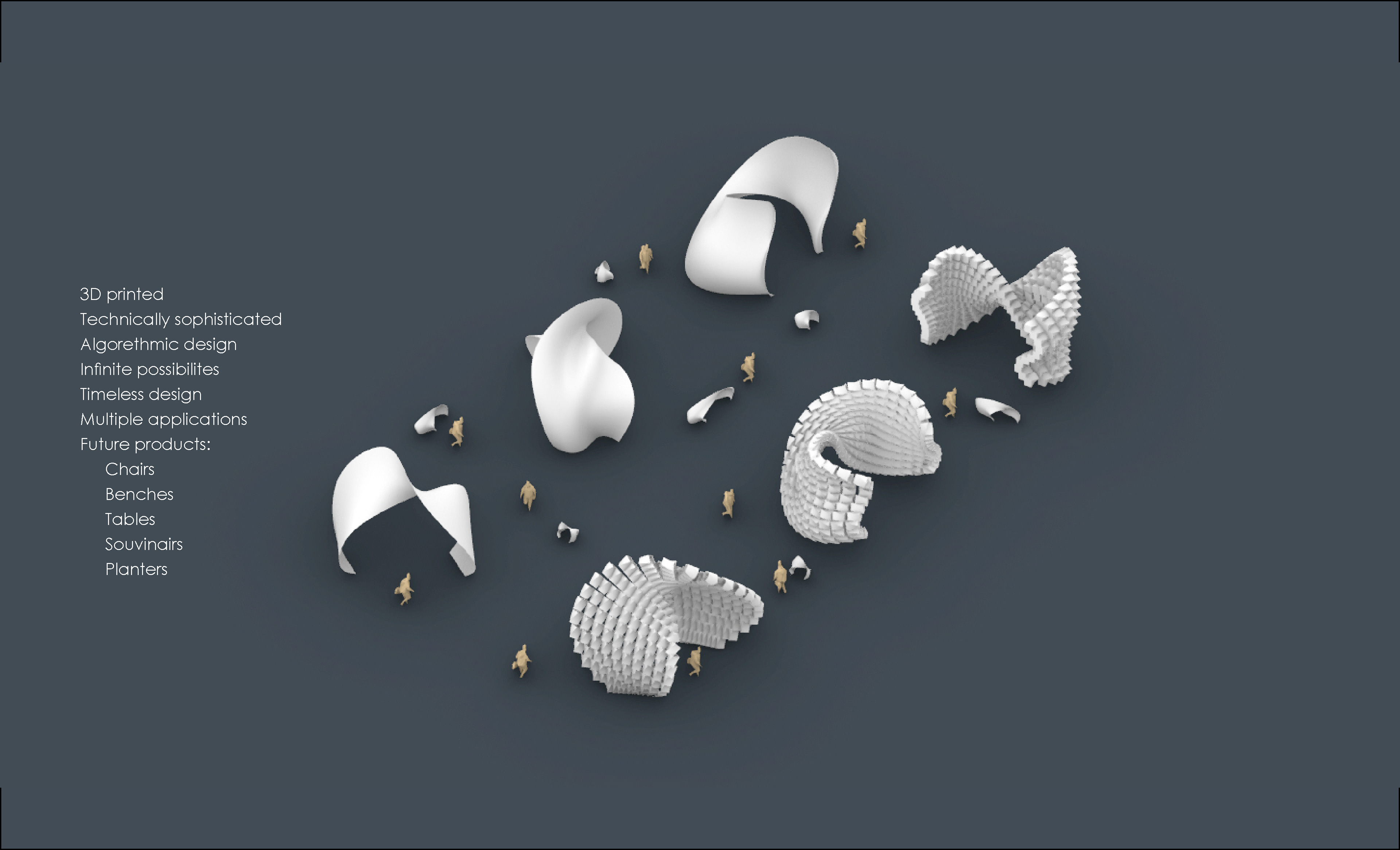
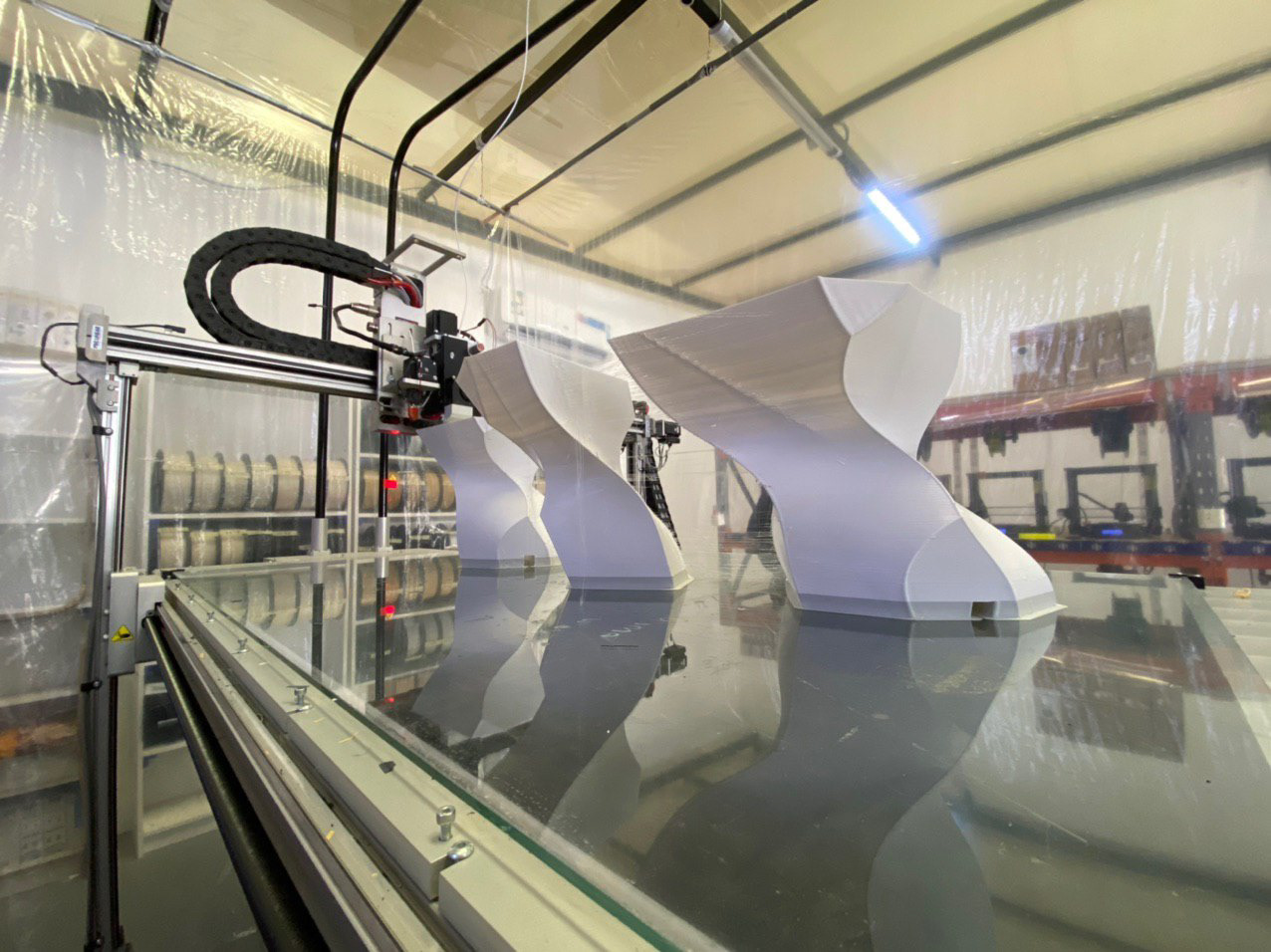
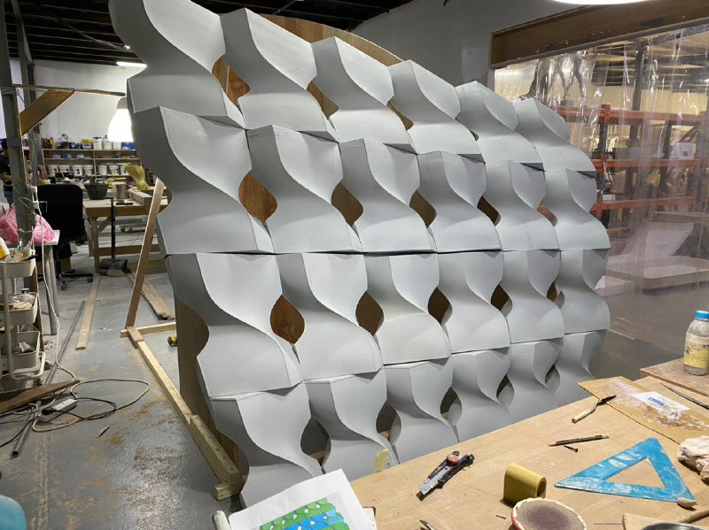
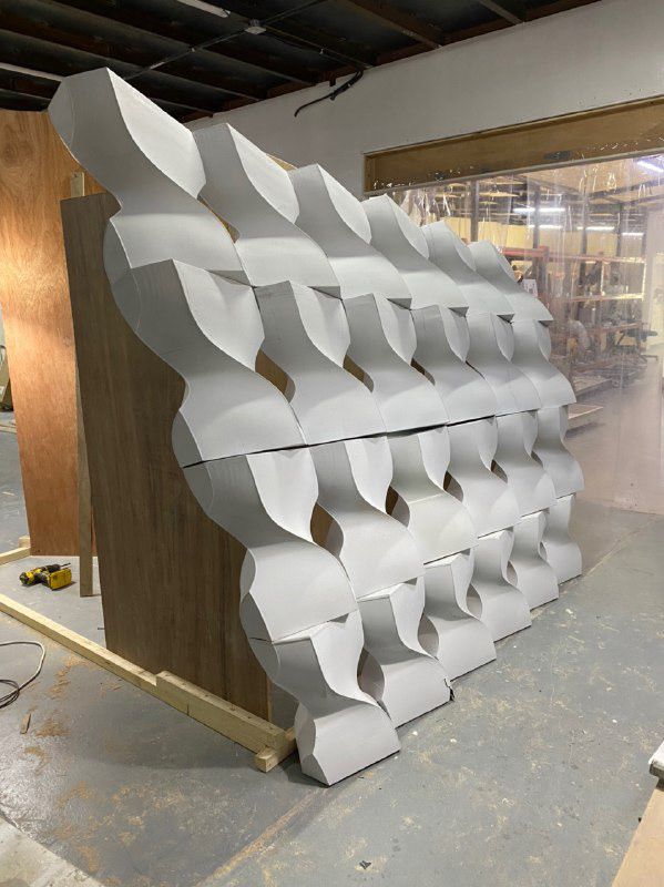
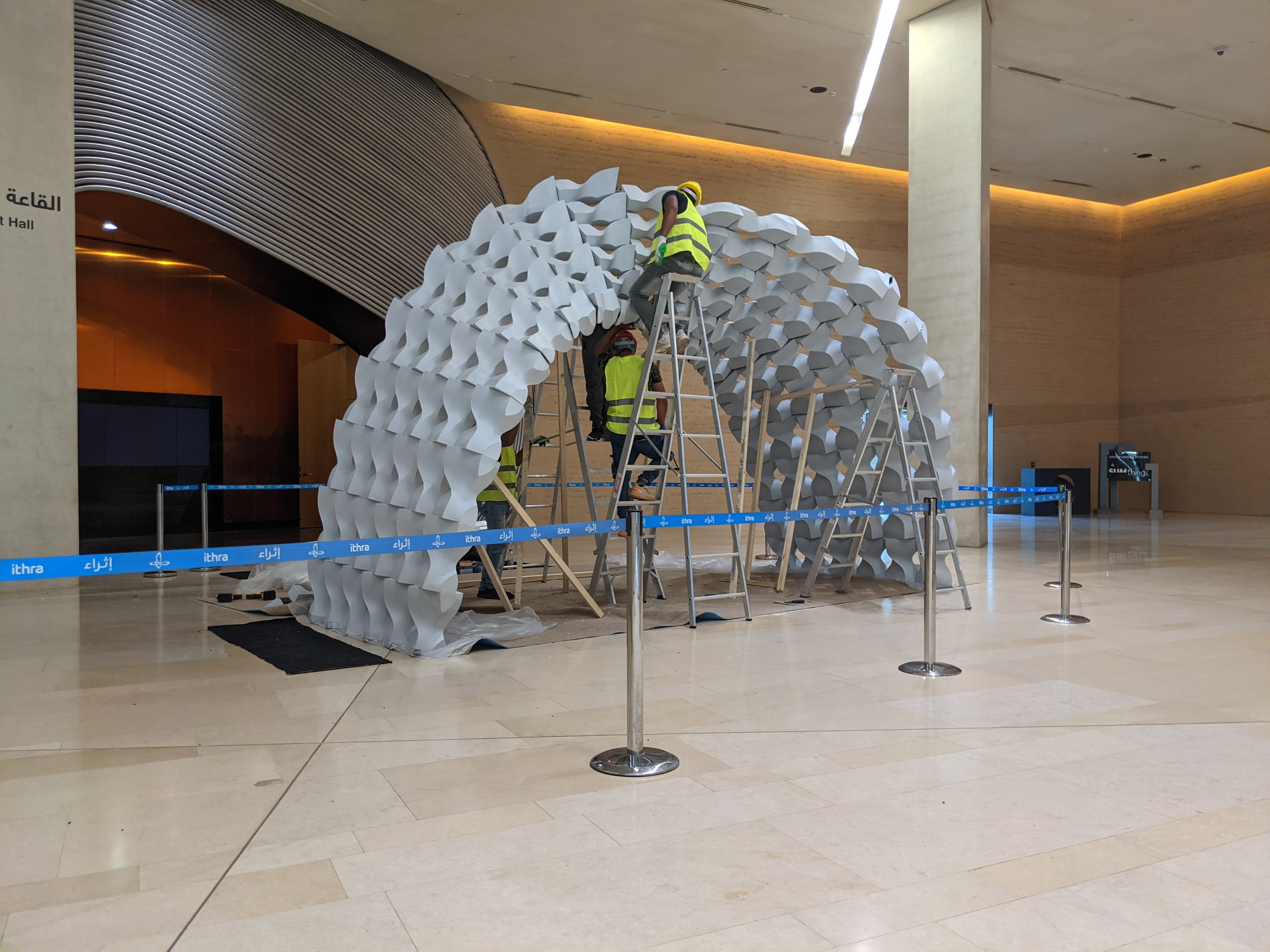
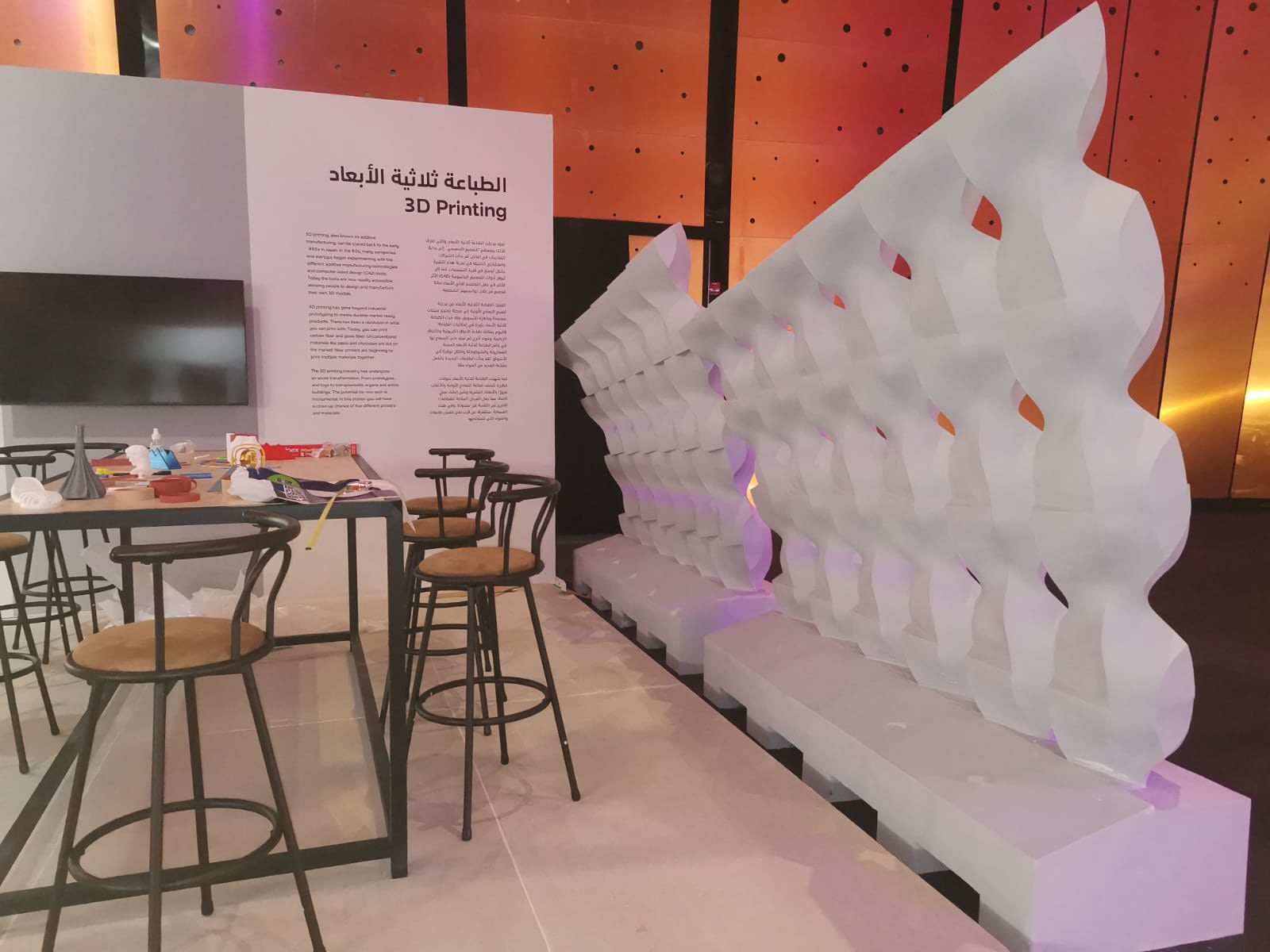
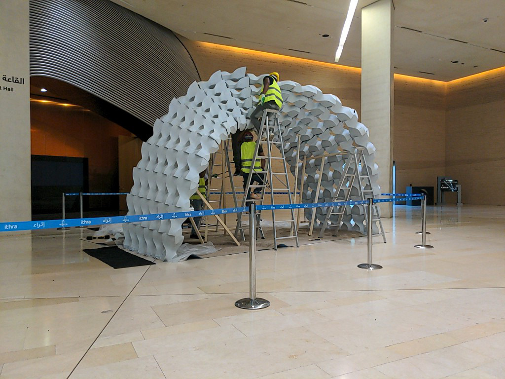
Noon pavilion is an assembly of 120 individually 3D Printed pieces that together form a twisting pavilion.
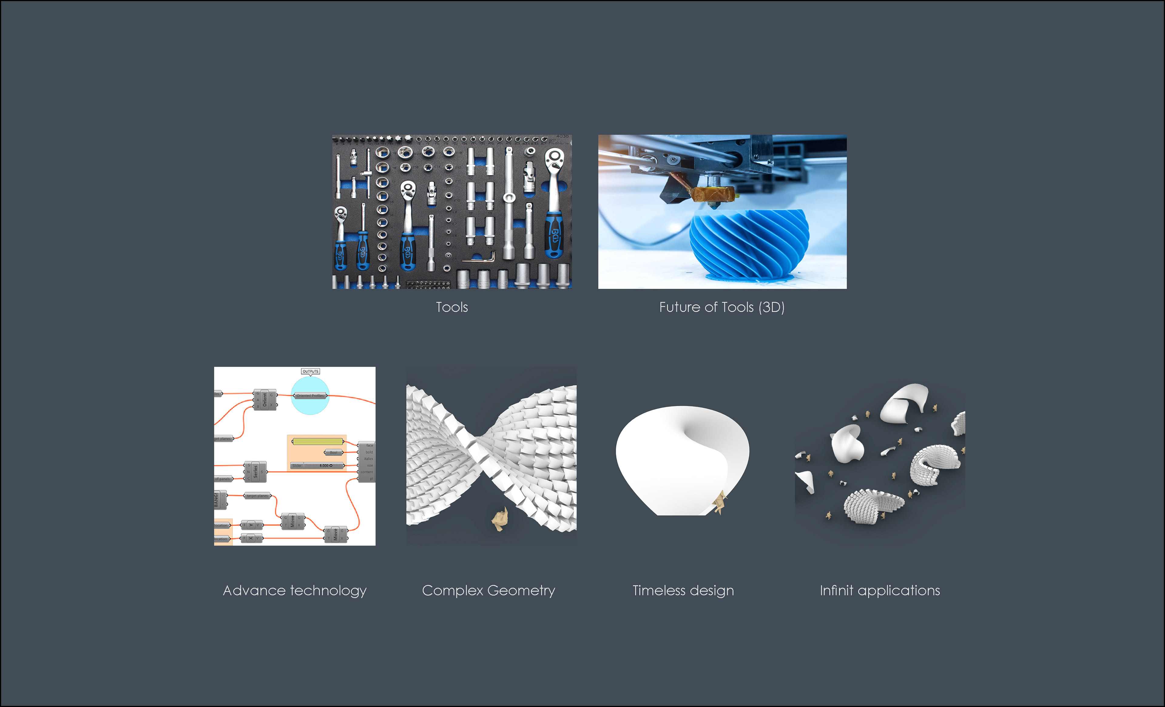
The intention was to leverage the robust growth of digital fabrication and FDM 3D printing. Even though 3d printing is a very flexible and versatile fabrication method, its constraints become more vibrant when it comes to large-scale assembly. Printing time, post-processing, and assembly.
The intention was to leverage the robust growth of digital fabrication and FDM 3D printing. Even though 3d printing is a very flexible and versatile fabrication method, its constraints become more vibrant when it comes to large-scale assembly. Printing time, post-processing, and assembly.

Computational design process
Form finding, optimization, modularization, structure, structural stability, unique pieces ready for 3D print
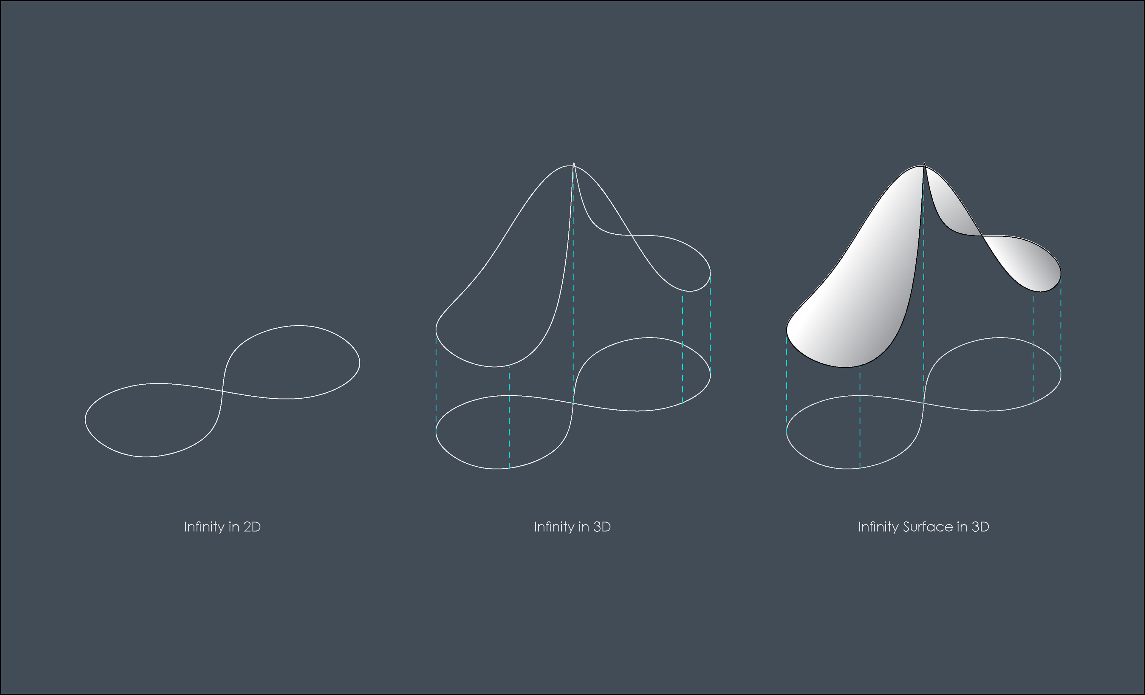
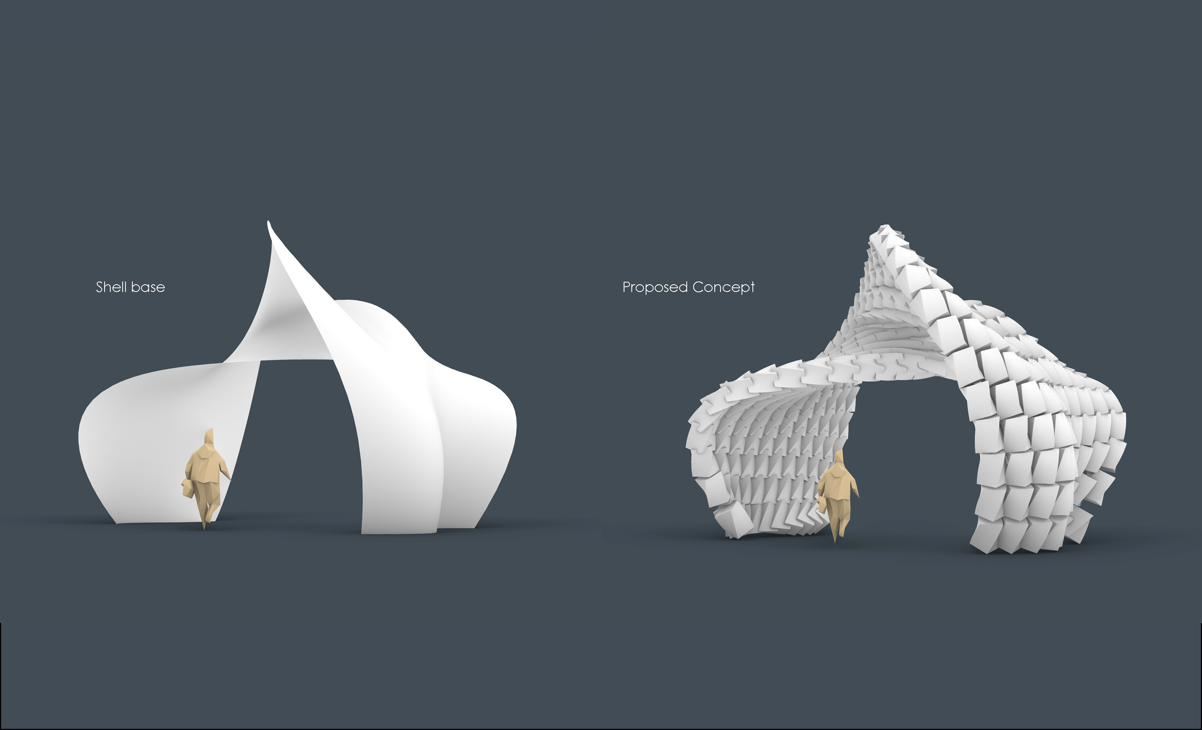
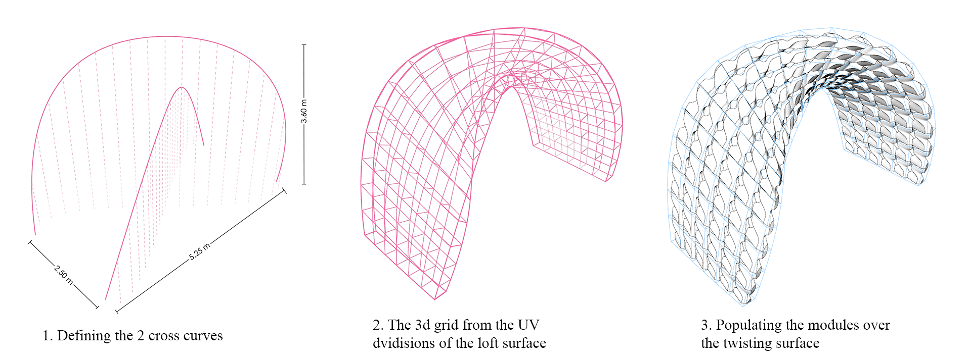
The overall form of the shell was generated and controlled by two crossed curves in 3-dimensional space. The two curves were then lofted to create a base surface for form development and initial stability analysis. Along the surface, a 3D grid was developed using the surface UV divisions to control the density and dimensions.
A single module was designed to produce an overall relevant and integrated design. The module then morphed into the 3D grid creating a series of deformed modules according to the curvature direction. Before the final modules were ready for 3D printing, a series of intermediate processes were developed and integrated into the parametric model to optimize the 3d printing and post-processing as well as the assembly process. Those processes could be categorized as follows:
A single module was designed to produce an overall relevant and integrated design. The module then morphed into the 3D grid creating a series of deformed modules according to the curvature direction. Before the final modules were ready for 3D printing, a series of intermediate processes were developed and integrated into the parametric model to optimize the 3d printing and post-processing as well as the assembly process. Those processes could be categorized as follows:
- The module geometry definition
- The planarization process and evaluation.
- The structural elements integration.
- Modules array and numbering.
- Assembly and installation.
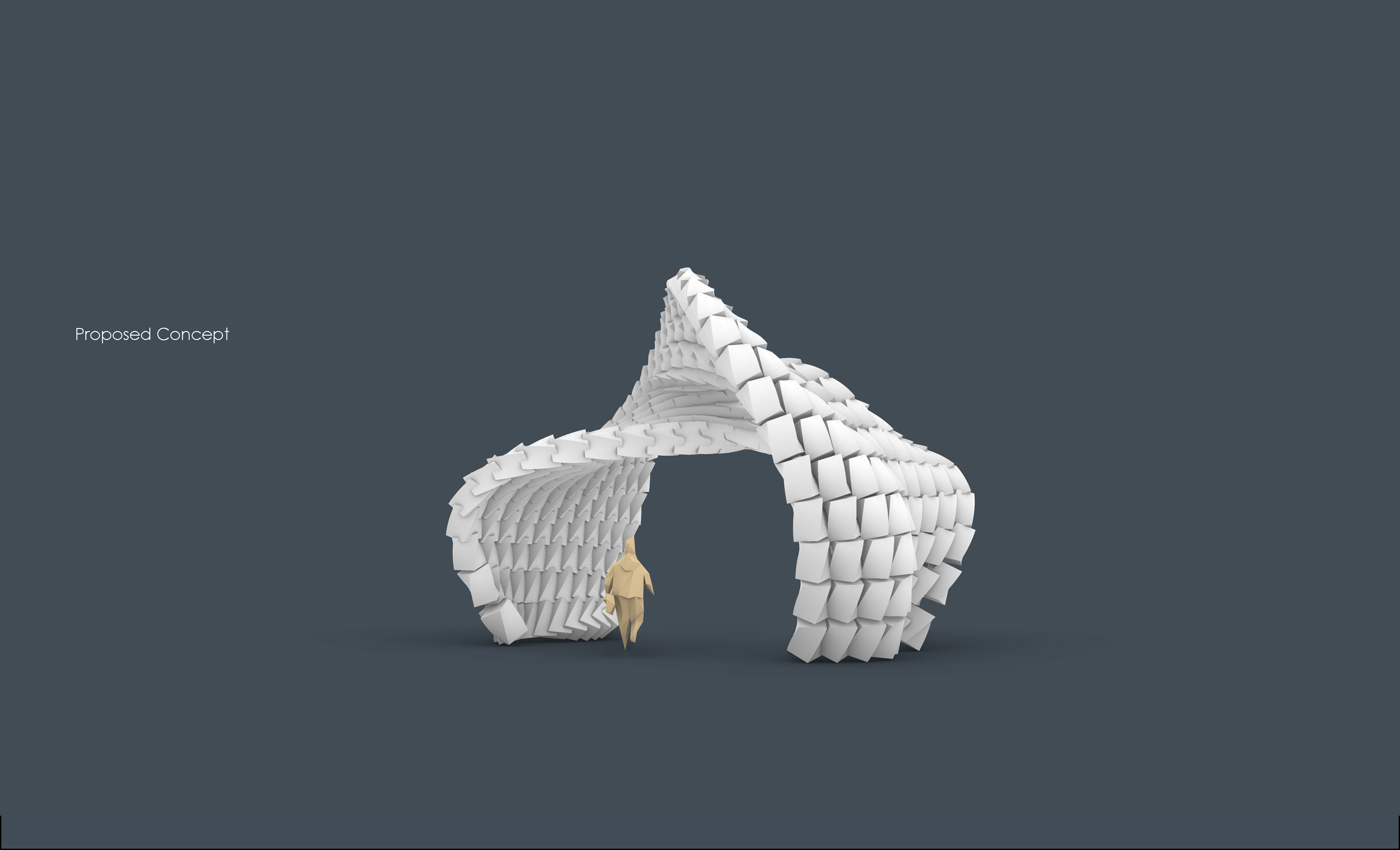
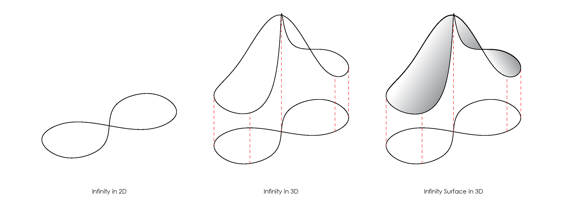
Concept development
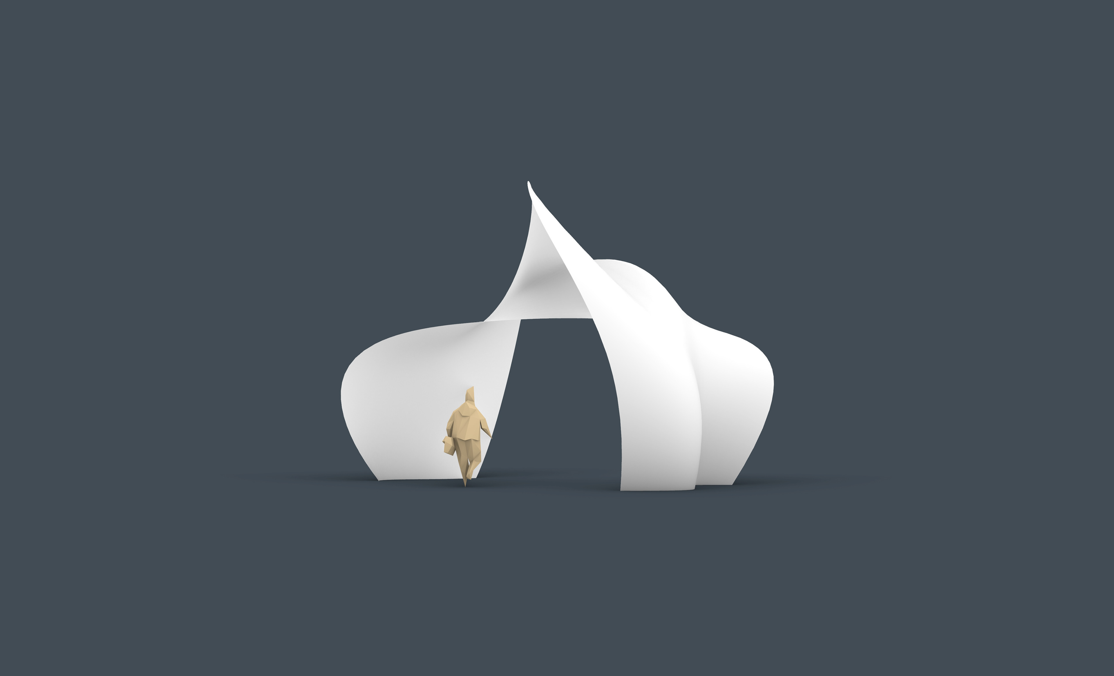
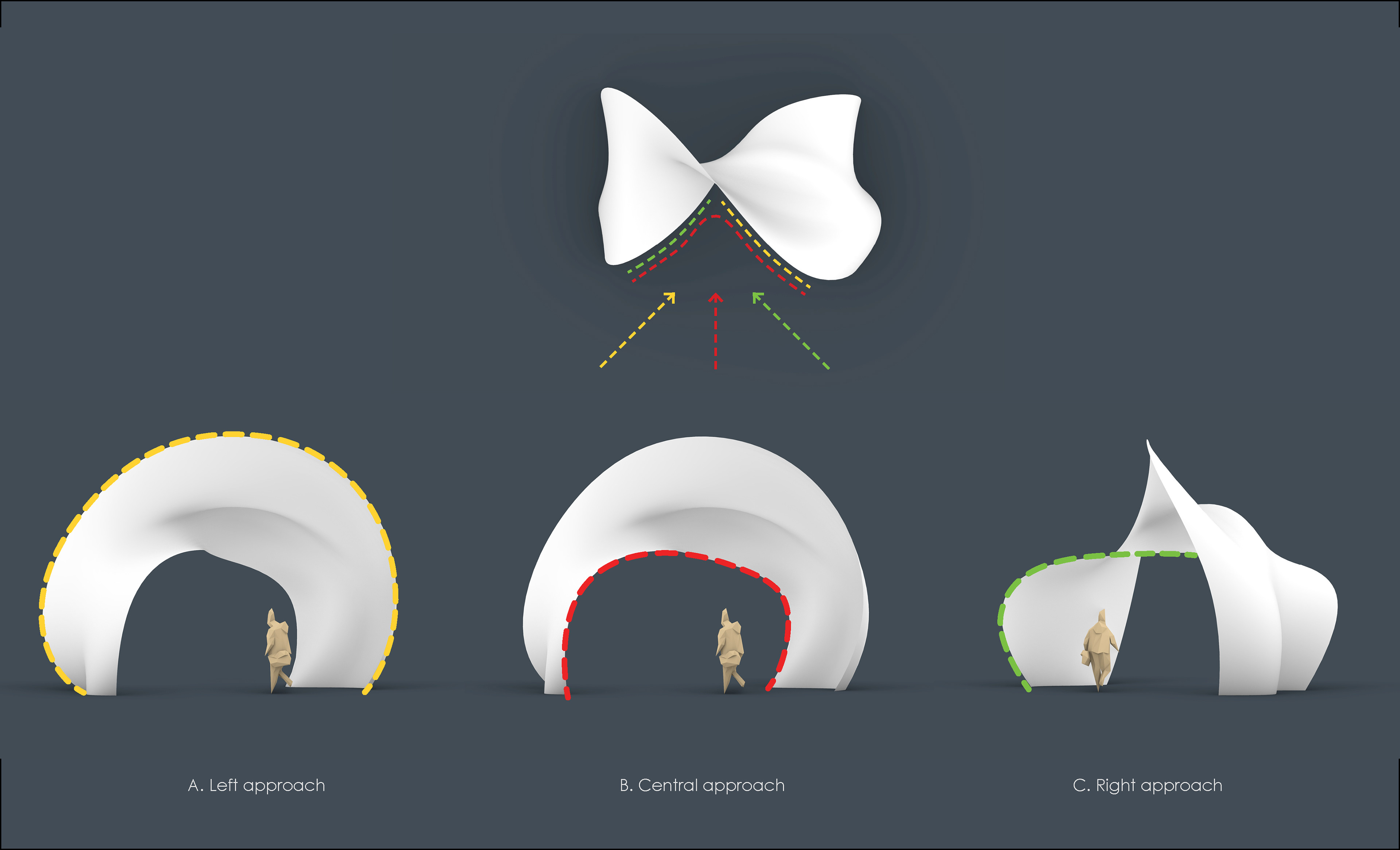
The design approach was to start from a simple twisted surface and use its UV grid to populate and morph modules across the surface generating unique individual pieces ready for 3D printing. The modules were designed to fit on the surface seamlessly after deformation and create one overall flow across the twisting surface. The specificity of the design is to follow a part-to-whole approach with the flexibility of whole-to-parts adaptation. The modules creating the pavilion were embedded with the information needed for printing and assembly such as structural cavities, connection mechanism, and surface alignment in 3-dimension. The following sections are explaining the design process in more detail.
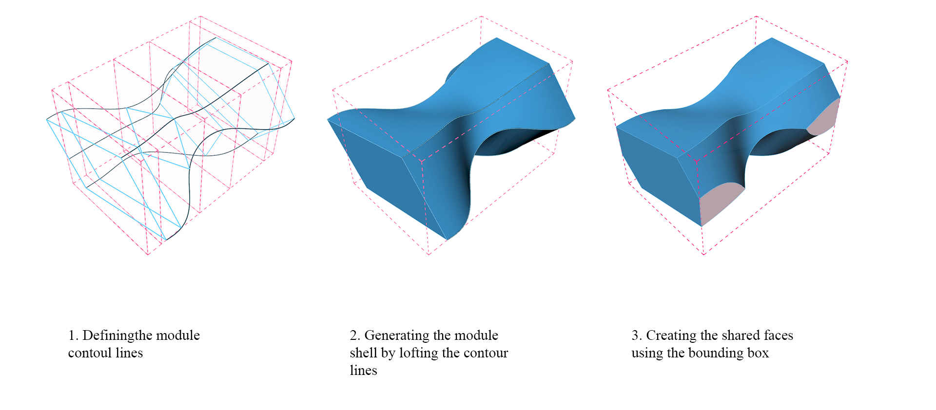
Concept adaptation
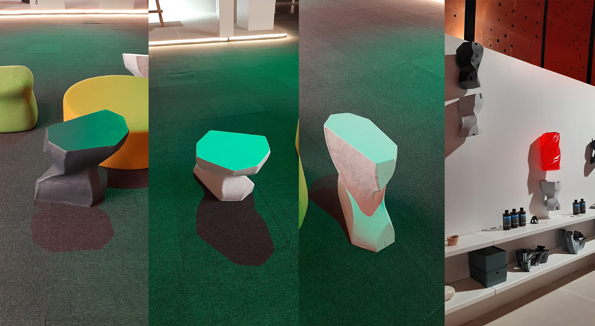
The strategy to develop the pavilion was to morph the modules into 3D grid boxes. The module was created within a bounding box for a better understanding of the shared faces between the modules. A 350mm by 350mm by 550mm box was set as the bounding box. By defining six cross sections, we got an interesting twisting module with corners protruding on the sides of the bounding box. The protrusions were trimmed by the bounding box to create flat surfaces shared between modules. One of the strategies to minimize the printing time was to soften the sharp edges of the polygons by filleting. This allows the printer to maintain its speed and avoid unnecessary deacceleration. The module was designed with the potential of being a byproduct of its own after disassembly.
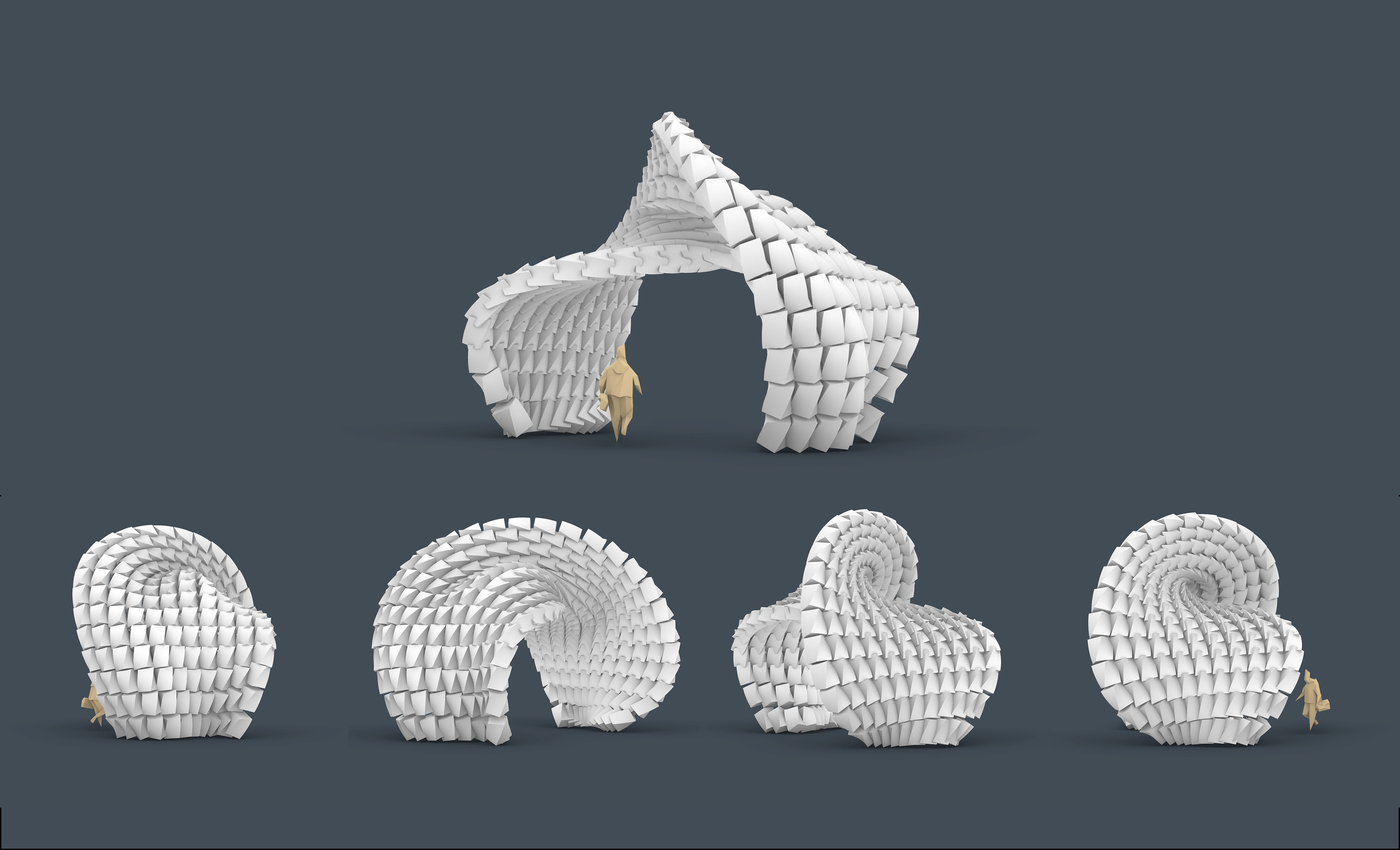
Adaptive use of the algorithm
Final Digital Design
Video starts at 1:10 for 3D printing, post processing, assembly, and final installation
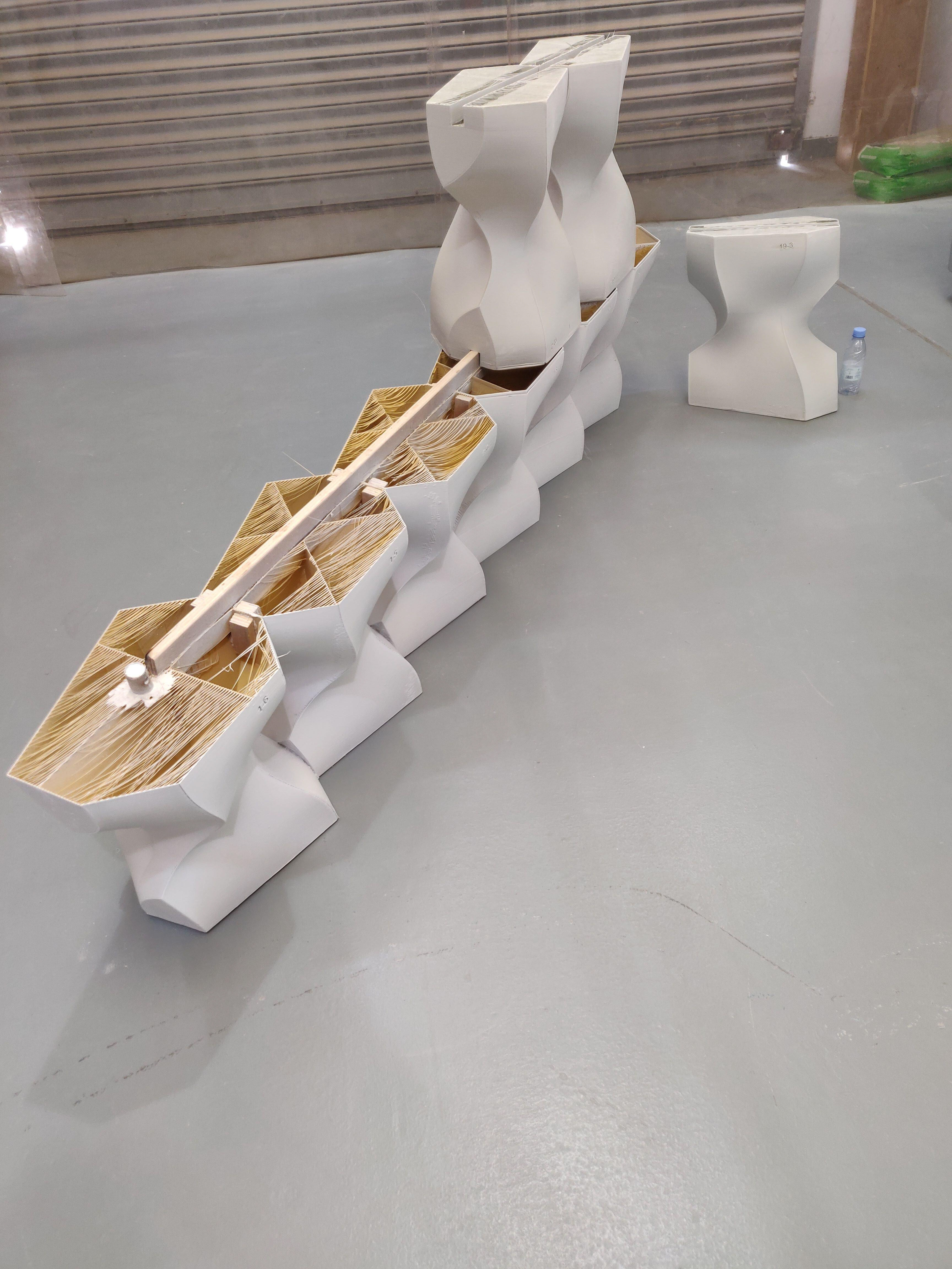
A concealed structural skeleton that runs through the modules was created and integrated during the design process. The structural elements were modeled as part of the parametric model to visualize collisions, check for structure visibility, and adjust the model accordingly. The structural members were booleaned out from modules in both directions to provide the required cavity for the assembly.
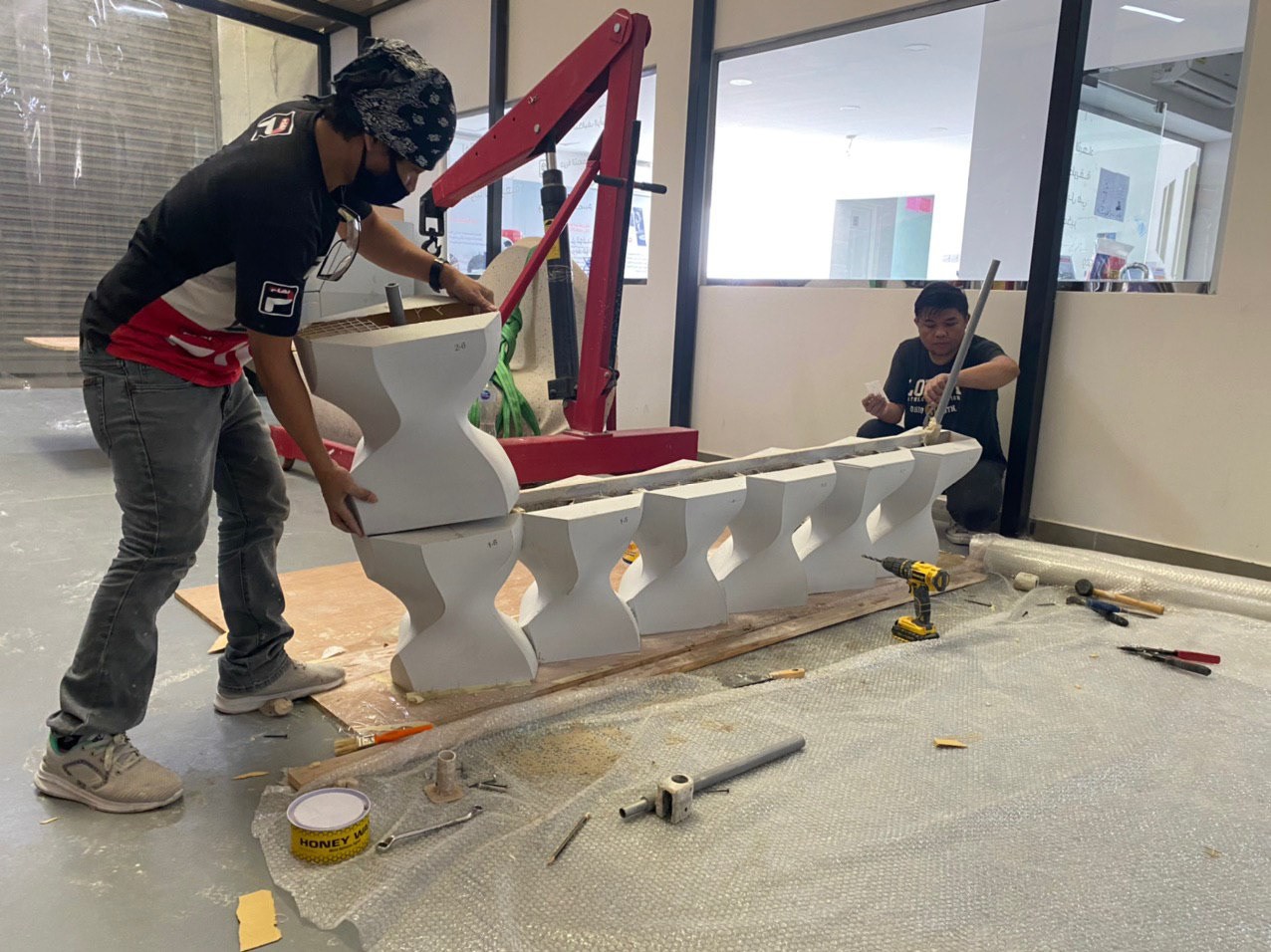
Each module was marked by two numbers at one corner to ensure precise and efficient assembly. The numbers show the exact position of each individual module on the pavilion. The first number indicates the row and the second one indicates the position of the module in that row.
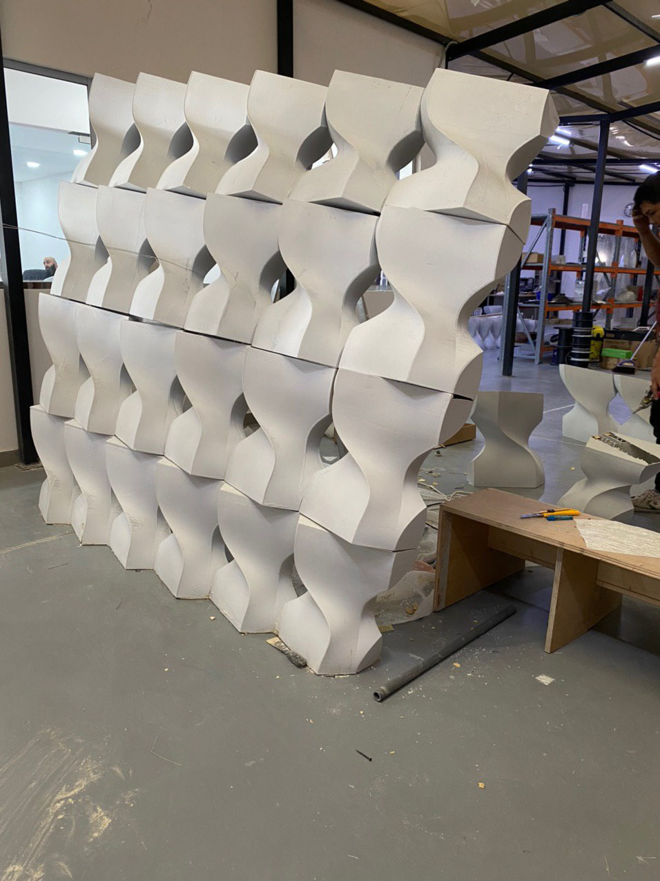
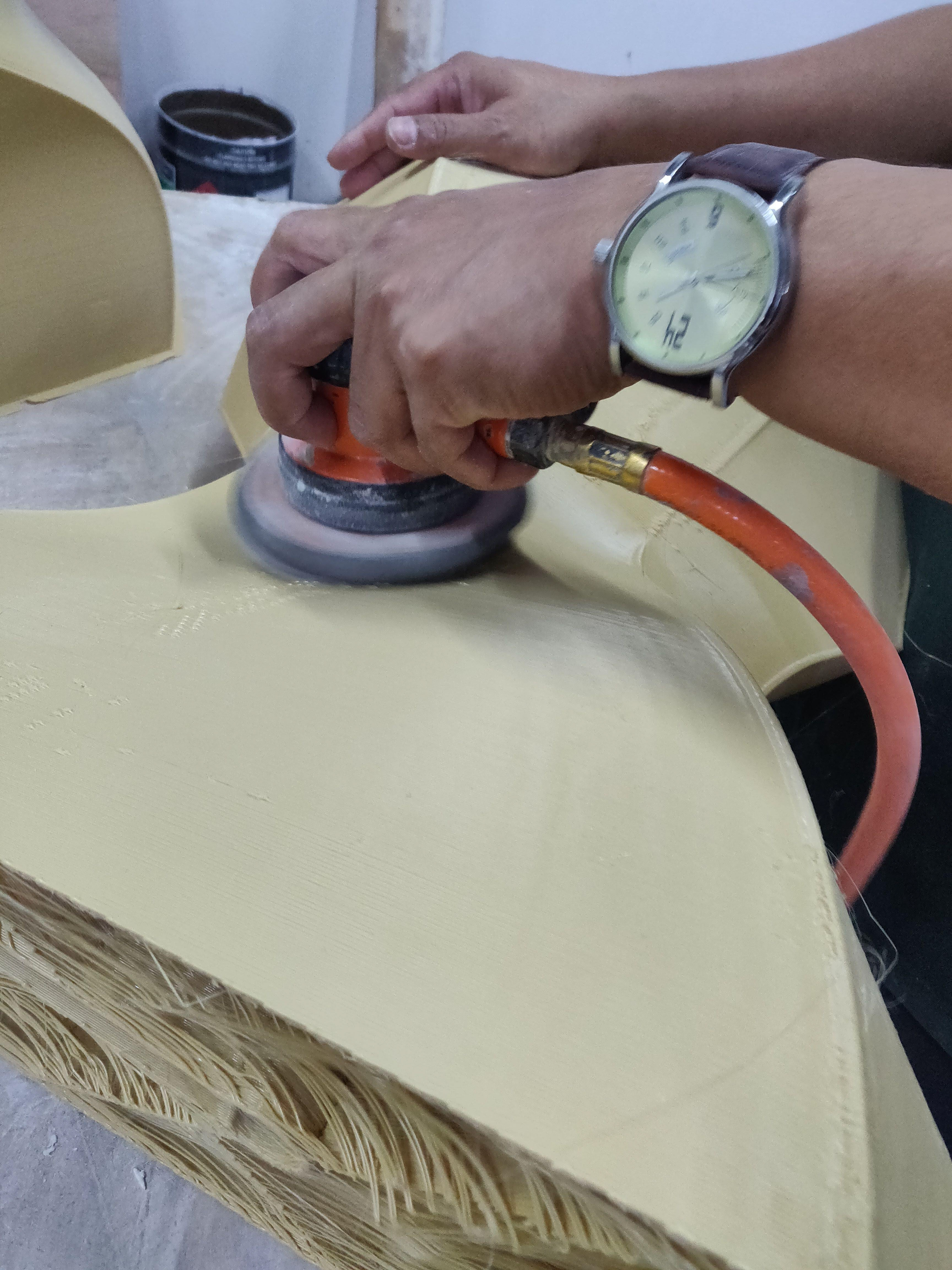
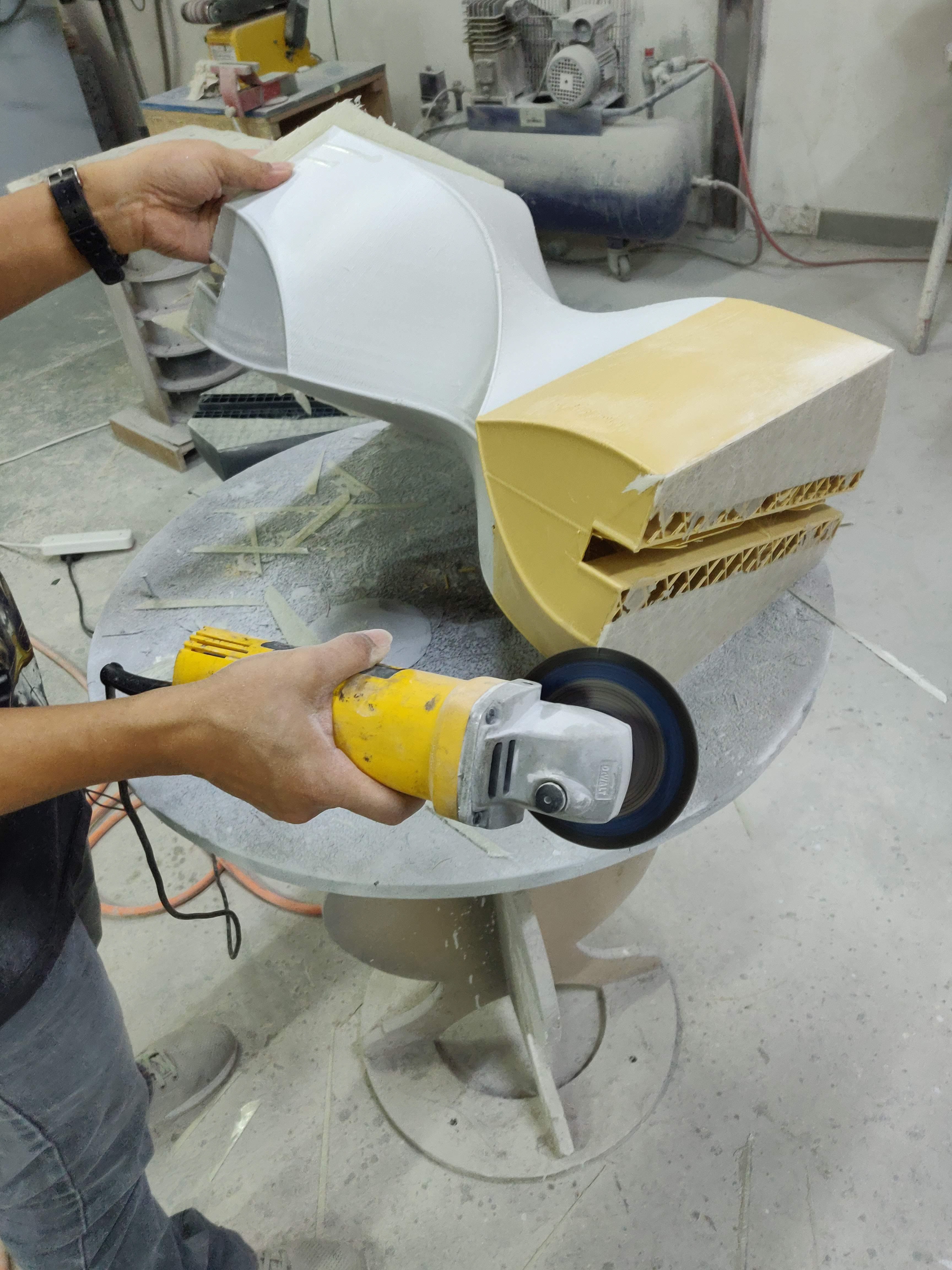
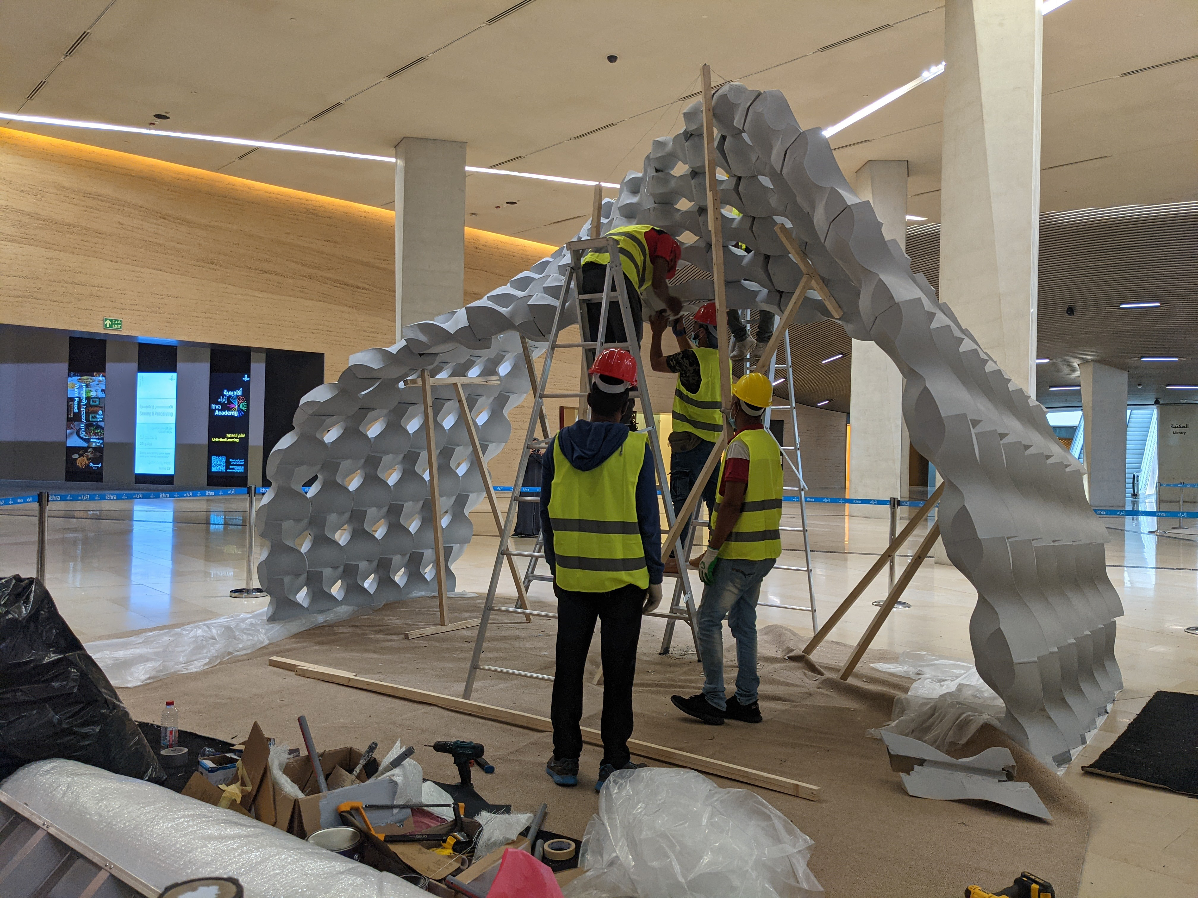
Fabrication Process
Video starts at 1:10 for 3D printing, post processing, assembly, and final installation
Fabrication Process Gallery
The individual modules were grouped side by side in rows and then stacked on top of each other. Each row was connected using a steel profile tying all modules together through a printed channel within the modules. Then, each row was connected to the above row by aligning the bottom and top surfaces of the modules using steel profiles through printed channels that cross each row.
Conclusion
This project is an exploration of how 3d printing as a fabrication affects the design process. The main challenges of this project were timing, structural stability, and assembly process. We overcame those challenges by having a robust parametric model for micro and macro adjustments, iterations, and optimization. A discrete design was inevitable considering the relatively small build volume of the 3d printers used for this project. Utilizing the 3d print capability of free forms, the design turned into a complex human-size 3d puzzle, but the integrating of underlying structure helped to avoid the complexity and guided the assembly process. In the end, the fabrication method influenced the design process to be more strategic and structured with a direct feedback loop between the parts and the whole.